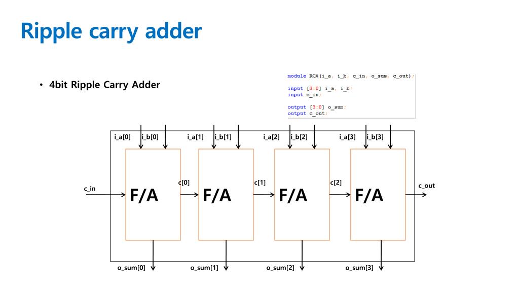
Half_adder f(input1,input2,answer,carry) įull_adder f(input1,input2,carry,answer,carry) Įndgenerate endmodule // : FPGA projects, Verilog projects, VHDL projects // Verilog project: Verilog code for N-bit Adder // Verilog code for half adder module half_adder(x,y,s,c) Įndmodule // half adder // fpga4student. Our product offerings include millions of PowerPoint templates, diagrams, animated 3D characters and more.// : FPGA projects, Verilog projects, VHDL projects // Verilog project: Verilog code for N-bit Adder // Top Level Verilog code for N-bit Adder using Structural Modeling module N_bit_adder(input1,input2,answer) is brought to you by CrystalGraphics, the award-winning developer and market-leading publisher of rich-media enhancement products for presentations. In this video i have explained the circuit diagram of 8 bit ripple carry adder with its verilog coding in structural model along with the xilinx ISE simulation. Then you can share it with your target audience as well as ’s millions of monthly visitors. The Verilog code for N-bit Adder is done by using Structural Modeling. To review, open the file in an editor that reveals hidden Unicode characters. We’ll convert it to an HTML5 slideshow that includes all the media types you’ve already added: audio, video, music, pictures, animations and transition effects. This post presents Verilog code for N-bit Adder designed for the co-processor. ripplecarryaddertb.v This file contains bidirectional Unicode text that may be interpreted or compiled differently than what appears below.

You might even have a presentation you’d like to share with others.

And, best of all, it is completely free and easy to use. Whatever your area of interest, here you’ll be able to find and view presentations you’ll love and possibly download. It has millions of presentations already uploaded and available with 1,000s more being uploaded by its users every day.

is a leading presentation sharing website.

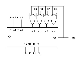
output C // The 1-bit carry/borrow status. module ripplecarryaddersubtractor(S, C, V, A, B, Op) output 3:0 S // The 4-bit sum/difference. The code for the full adder is also shown for completeness. Constraints on Input Labels for Every State Sk (From -124) 1. The following Verilog code shows a 4-bit adder/subtractor that uses the ripple carry method. Each bit of a vector must be mapped individually S 1 S 2 S 0 S 3 0/0 N/Sh 1/1 /1 /1 /1 Next State Present Output (Sh) N0 N1 N0 N1 S 0 S 0 S 1 0 1 S 1 S 2 S 2 1 1 S 2 S 3 S 3 1 1 S 3 S 0 S 0 1 1 Present State Figure 4-2 Control State Graph and Table for Serial Adder.


 0 kommentar(er)
